Jointing fittings
Jointing fittings are designed to connect insulators, to keep required distance, to joint the parts of multiple insulator string, to attach the insulator strings to the towers.
The fittings should be designed for mechanical loading caused by tensioning and weight of the conductors as well as other elements during normal working conditions, for additional loading caused by wind or frost. They should withstand the maximum strength guaranted by the manufacturer. The fitting must not be damaged. This is guaranted breaking strength, in catalogue refered as breaking strength.
The fittings should be designed for electrical loading. Nominal short-time current Ith per 1 second is based on the density of short-time current 70 A/mm², when starting temerature is 30 °C and max. temperature app. 400 °C, loading from 1 kN up to working loading.
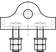
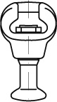
Double ballsC 1
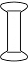
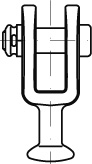
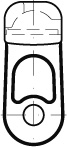
Clevis ballsC 2
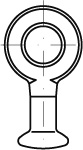
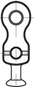
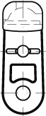
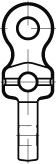
Ball eyesC 3
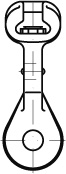
Ball eyes straight for arcing fittingsC 4
Ball eyes twisted for arcing fittingsC 5
Oval ball eyes for arcing fittingsC 6
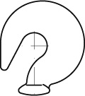
Hook ballsC 7
Socket ballsC 8
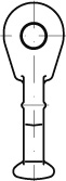
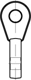
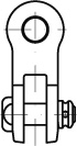
Socket eyesC 9
Socket eyes straight for arcing fittingsC 10
Socket eyes twisted for arcing fittingsC 11
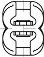
Double socketsC 12
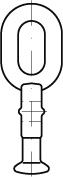
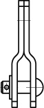
Double eyes straightC 13
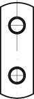
Double eyes straight for arcing fittingsC 14
Double eyes twistedC 15
Double eyes twisted for arcing fittingsC 16
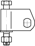
Clevis straps straightC 17
Clevis eyes twistedC 18
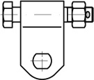
Clevis strapsC 19
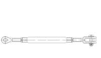
Adjustable extension strapsC 20
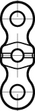
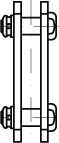
Double clevisesC 21
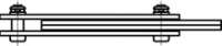
Jointing fittingsC 22
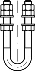
U - BoltsC 23
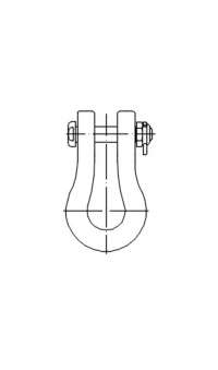
ShacklesC 24
Suspension hingesC 25
Strain hingesC 26
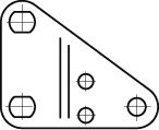
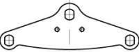
YokesC 27
HingesC 28